Diagnosing Mezzanine Connector Failure
Simultaneous loss of HD-SDI, HDMI, audio, and all storage is the signature of this single failure.
- None required for diagnosis
- Torx T6 and T8 screwdrivers (if proceeding to repair)
- Stereo microscope or strong magnifying glass (for visual trace inspection)
Overview
The most common RED ONE MX failure is lifted PCB traces on the CPU_IO board near the 180-pin Samtec QTH-090-06 mezzanine connector. This connector routes all digital I/O (video outputs, audio, and storage interfaces) through a single high-density interface. When thermal cycling stress cracks traces near this connector, all of those subsystems fail simultaneously.
This guide covers diagnosis only. If the failure is confirmed, see the Repairing Broken Traces Near the Mezzanine Connector guide (planned) for the repair procedure.
The Diagnostic Signature
Mezzanine trace failure produces a very specific pattern. All four of these must fail simultaneously:
| Output | Normal state | Failure state |
|---|---|---|
| HD-SDI | Signal present on connected monitor/recorder | No signal |
| HDMI | Signal present | No signal |
| XLR audio input | Audio recorded normally | No audio in recording |
| Storage (CF + SSD + RED DRIVE) | Media detected and accessible | All show as absent or unrecognised |
If only some of these fail, the fault is likely elsewhere:
- Only storage fails: check the iVDR connector and SSD module
- Only audio fails: check XLR cable and module
- Only SDI fails: check cable and GS2978 SDI driver chip (AUDIO_PCI board)
The key diagnostic feature is simultaneous total failure of all four subsystems. If you see that pattern, the mezzanine connector traces are the most likely cause.
Steps
Connect a known-good HDMI or HD-SDI monitor. Connect a known-good CF card. Connect a known-good REDMAG SSD. Connect a known-good XLR microphone or source. Power on the camera and check each output.
If all four fail with known-good accessories, the fault is almost certainly in the camera body, not the accessories. Proceed to step 2.
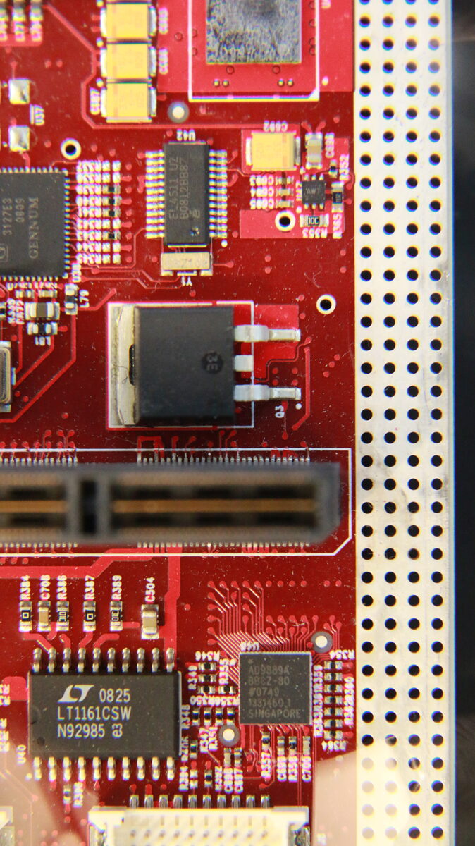
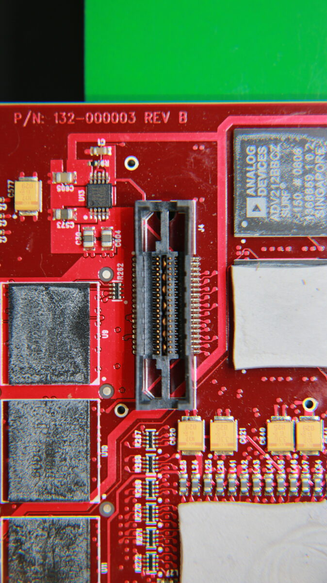
The CPU_IO board is the large red PCB accessible after removing the camera's rear panel. The 180-pin mezzanine connector (labelled J7 on the board) runs horizontally across the board and connects the CPU_IO board to the AUDIO_PCI board below it.
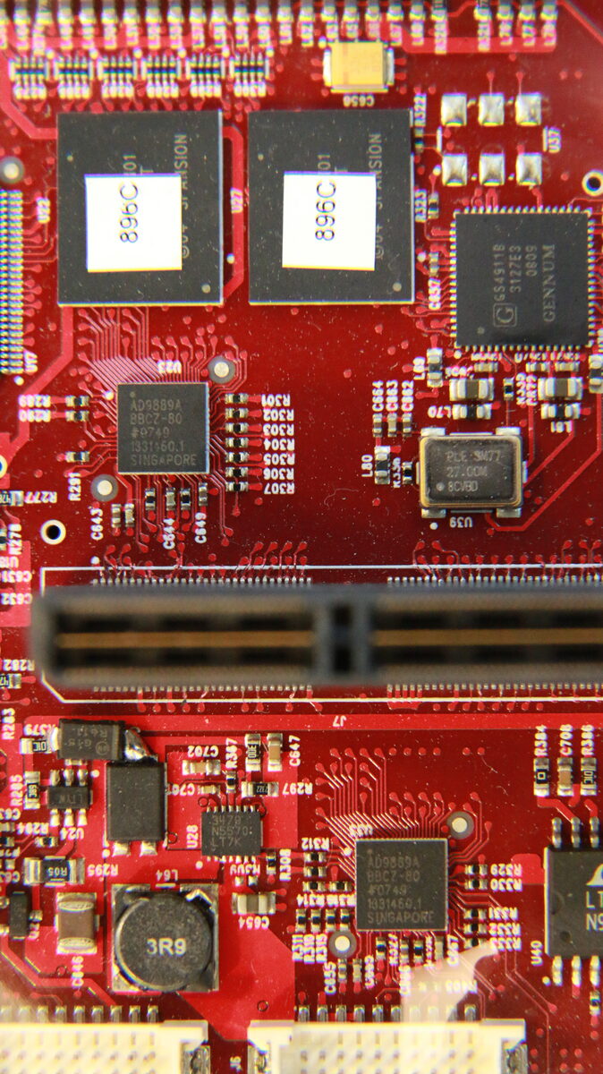
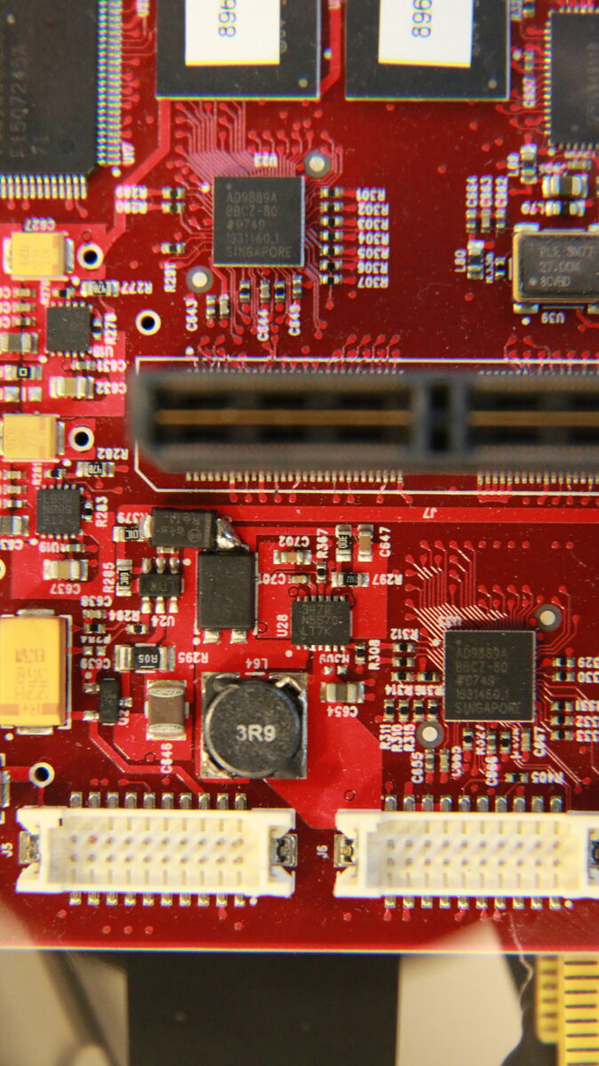
Look for any of the following around the connector body on the CPU_IO board:
- Hairline cracks running across copper traces (appears as a thin dark line through a trace)
- Lifted traces (trace visually separated from board surface)
- Cold solder joints at the connector pins (dull, grainy, or bulging solder)
- Physical deformation from impact or thermal stress
The traces most commonly affected are on the CPU_IO board side, within 5mm of the connector body. The damage is often subtle and requires at minimum a strong loupe or magnifying glass; a stereo microscope is ideal.
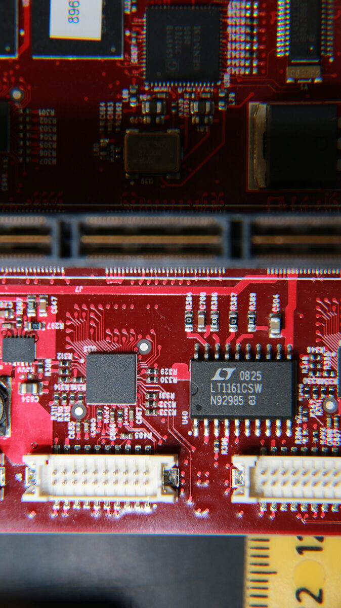
With the boards separated (camera fully disassembled), use a multimeter on continuity mode to probe traces on the CPU_IO board near the mezzanine connector. A broken trace will show no continuity between two points that should be connected.
Identifying which specific traces to test requires the board schematics - these are under active research in the r1mx project. See the Hardware Reference page for current status.
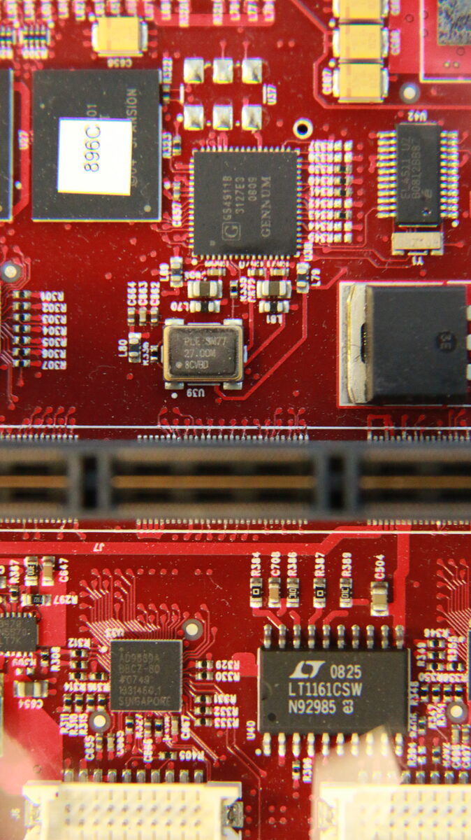
Photograph the area under magnification. Note the exact location of any damaged traces. This documentation is valuable for:
- Planning the trace repair
- Contributing findings to the r1mx project
- Getting help from the community (post photos to REDuser.net RED ONE forum)
What to Do Next
| Finding | Next action |
|---|---|
| Clearly lifted or cracked traces visible | Proceed to trace repair guide (Hard difficulty) |
| Connector physically damaged or pins bent | Connector replacement required - seek professional service |
| No visible damage found | Perform continuity test; or send to qualified repair technician |
| Fault not reproducible | May be intermittent connection - clean and reseat connector once |
Board Reference Photos
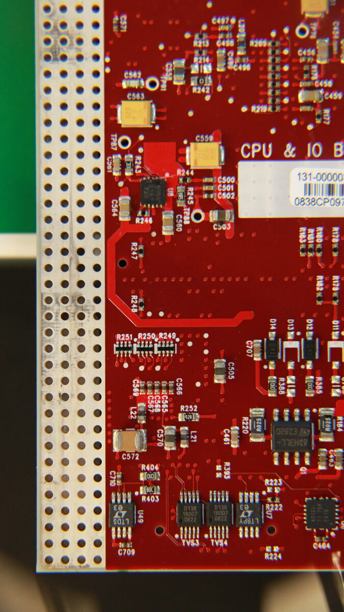
These are Kyle Simukka’s photos of a RED ONE MX CPU_IO board taken during the r1mx reverse engineering project (July 2020). Click any image for full size.
See Also
- Hardware Reference - full board documentation and IC list
- Camera Will Not Boot diagnosis - planned guide