REDMAG SSD Replacement Module
Community-designed replacement for the original RED iVDR SSD module, using modern SSD drives.
- 3D printer (FDM, 0.2mm layer height recommended)
- Soldering iron (fine tip)
- Flux (no-clean)
- Small flathead screwdriver
- Calipers (for fit verification)
- CA adhesive (cyanoacrylate, for assembly)
- Custom PCB (Gerber files in r1mx repository)
- Amphenol 10079510 iVDR connector (replacement for EOL 10033998-002LF)
- M.2 NVMe SSD (compatible drive, see notes below)
- M.2 to mSATA or SATA adapter (per chosen PCB design)
- 3D printed enclosure (STEP/STL files in r1mx repository)
- M2 or M3 hardware (screws and inserts, per BOM)
Overview
Original RED iVDR SSD REDMAG modules used spinning hard drives or early SSDs that are now end-of-life. The iVDR connector itself (Amphenol 10033998-002LF) is also discontinued. This guide documents a community-designed replacement module that uses a modern M.2 SSD inside a 3D-printed enclosure with a replacement iVDR connector.
This design was pioneered by Troy Grundstad and documented on REDuser.net. The r1mx project has incorporated these findings and is developing updated files.
Background: The iVDR Standard
REDMAG modules use the iVDR (Information Versatile Disc for Removable usage) interface, which is a hot-swappable storage interface standard developed in the early 2000s for consumer electronics. RED ONE used iVDR as a removable storage bay.
The original Amphenol iVDR connector (10033998-002LF) is end-of-life. The replacement connector is the Amphenol 10079510, which has a compatible footprint and pinout.
Design Evolution
Troy Grundstad’s original build documents the full design process from CAD model to finished module:
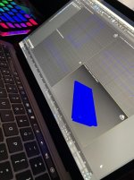
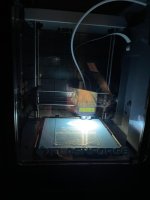
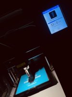
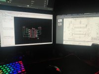
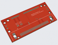
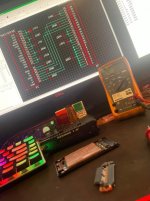
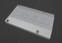
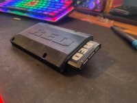
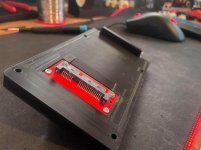
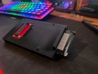
Images: Troy Grundstad / REDuser.net thread 3773957. Used with attribution.
The SSD Side Module Requirement
To use a REDMAG SSD module, the camera must have the SSD Side Module installed. The SSD Side Module is the physical casing that provides the REDMAG bay and facilitates the iVDR connector interface. It replaces the CF Module or Hard Drive Module on the camera’s left side.
This module is not a failure point - it is simply the required physical bay for REDMAG operation. If your camera currently uses a CF Module or RED DRIVE, you will need the SSD Side Module before a REDMAG will function.
The r1mx project is developing open-source replacement designs for the SSD Side Module enclosure. See the Firmware and Storage page for current status.
SSD Compatibility Notes
Not all M.2 SSDs work with the RED ONE MX. The camera was designed for ATA/SATA storage and has specific timing and model-string requirements.
Key findings from the r1mx research:
| Drive type | Compatibility | Notes |
|---|---|---|
| Original Toshiba HG3 SSD (from RED) | Confirmed working | Hard to source; typically sourced from dead modules |
| Other SATA SSDs with ATA model string reprogramming | May work | Firmware patch (build 32.1, in development) aims to remove this restriction |
| NVMe SSDs via M.2 adapter | Not currently compatible | SATA only interface |
The r1mx firmware project (build 32.1) is specifically targeting expanded SSD compatibility. See the Firmware Reference page for details.
Build Steps
Visit github.com/simukka/r1mx
and download the REDMAG module design files from the ssd_drive/ directory.
Review the README for the current revision status before ordering parts or starting a print.
The Gerber files can be uploaded to any PCB fabricator (JLCPCB, PCBWay, OSH Park, etc.). Order the Amphenol 10079510 iVDR connector from Mouser or Digi-Key. The iVDR connector is the most critical component - verify the part number before ordering.
Print with PETG or ABS for heat resistance (PLA may soften in a warm camera bag or in-camera). A 0.2mm layer height provides sufficient detail for the connector cutout and slot tolerances. Print with at least 3 perimeters and 40% infill for rigidity.
Print a test fit piece first before committing to a full enclosure print. The iVDR connector cutout dimensions are critical.
The Amphenol 10079510 is a fine-pitch surface mount connector. Apply flux liberally to the pads. Tack two corner pins first to align the connector, then solder across all pins. Inspect under magnification for solder bridges. Clean flux residue with isopropyl alcohol.
Following the PCB layout, install the M.2 SSD or adapter. Assemble the PCB into the 3D printed enclosure per the assembly notes in the repository. Verify that the iVDR connector is correctly aligned with the enclosure cutout before final assembly.
Insert the module into the SSD Side Module bay (on the camera) without the enclosure screws fully tightened. Verify it seats fully and the iVDR connector engages. Look for any interference in the bay. Adjust the print or enclosure dimensions if needed before fully assembling.
Insert the assembled module into the camera. Power on and check the media menu. If the drive is detected, attempt a format and test recording. If the drive shows as "INCOMPATIBLE", the drive model string may need to be reprogrammed. See the Firmware Reference for current compatibility research.
Troubleshooting
| Problem | Possible cause | Action |
|---|---|---|
| Module not detected at all | iVDR connector not seated / soldering issue | Check connector seating; inspect solder joints |
| Drive shows “INCOMPATIBLE” | SSD model string not on RED approved list | Reprogram model string (advanced); or wait for firmware 32.1 |
| Module fits loosely in bay | Print tolerance too loose | Reprint enclosure with slightly reduced tolerances |
| Camera freezes when module inserted | Power issue or connector short | Check for solder bridges; test with different SSD |
Contributing
This guide is actively being updated as the r1mx project develops the design files. If you have built a module, your photos, measurements, and notes are valuable. See the Contributing Guide for how to submit.
See Also
- Firmware Reference - SSD compatibility and firmware 32.1 development
- Components Reference - original REDMAG specifications
- r1mx Repository - design files, Gerbers, BOM